How does a pressure transmitter work?
To understand how a pressure transmitter works, it is enough to focus on its two key elements: One is the pressure sensor, which detects the pressure of the medium and converts it into an electrical signal. The other is an application specific integrated microchip. It is needed to convert the generated electrical signal into a normalised output signal.
Pressure sensor
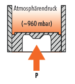
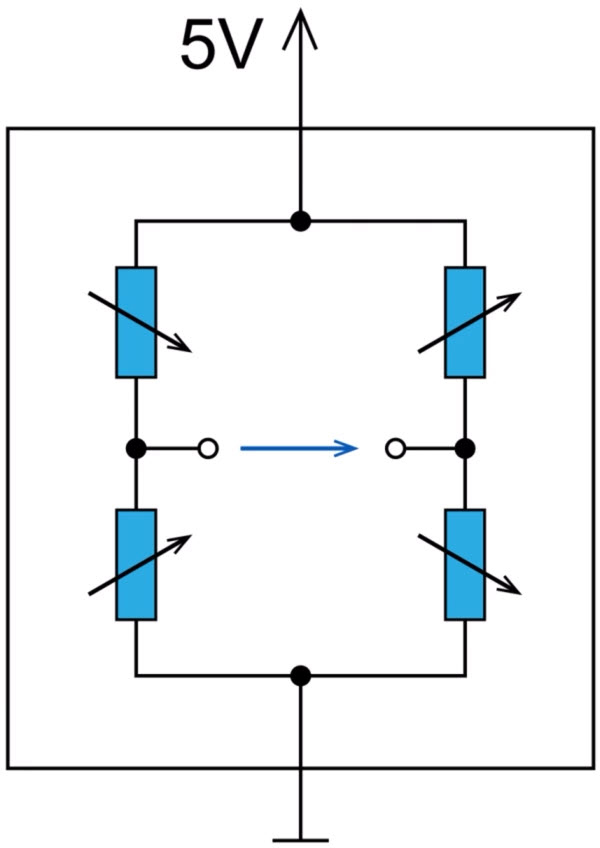
The pressure sensor consists of a thin-film-on-steel cell (Figure 1), where the resistance bridges are applied as a thin film to the surface of a steel sensing element. This thin film is only a few atomic layers thick. When pressure is applied to the pressure sensor, its membrane deforms at predefined points. The resistors are placed exactly at these points and change their value when stretched or compressed. There are four strain resistors on the sensing element. Two resistors each form a path. A bridge can be formed in the middle where the voltage can be measured. This bridge is called a Wheatstone bridge. When there is no pressure, all the resistors have the same value, so there is no voltage between the left and right paths.
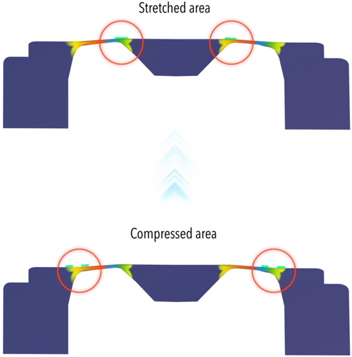
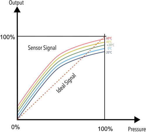
When pressure deforms the membrane, two resistors are compressed, and two resistors are stretched. This increases the electrical resistance in the stretched areas (Figures 2 and 3). On the other hand, the pressure decreases in the compressed areas. This changes the state of the resistance bridge, and a signal is generated. However, the measured signal is not linear and varies depending on the ambient temperature. This is because the temperature has a strong influence on the resistance of the bridge (Figure 4).
Application specific microchip
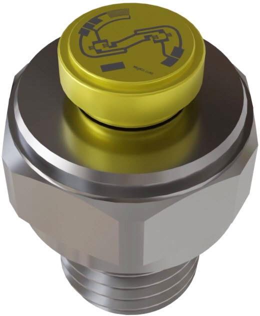
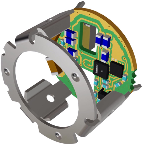
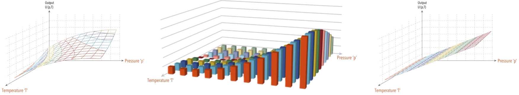
To obtain a linear, accurate and temperature independent measurement signal from the measured signal, intelligent electronics are required. The electronics corrects and amplifies the measurement signal, e.g., a 10-millivolt signal is transformed into a 10-Volt signal. The correction values obtained are stored in the application specific microchip (also called Application Specific Integrated Circuit - ASIC, Figure 5). These values are determined and stored individually for each pressure transmitter. To determine the correction values, a precisely defined pressure is applied to the ready-mounted pressure transmitter and the signal is measured. For the applied pressure, the correction values can be calculated. The process is then repeated at different temperatures. This allows the correction values for temperature compensation to be determined. The correction values determined in this way are then stored in the chip. In this way, a linear and standardised measurement signal can be generated from the raw signal of the sensing element. And this over the entire pressure and temperature range (Figure 6). This standardised measurement signal can be transmitted to higher-level control systems.
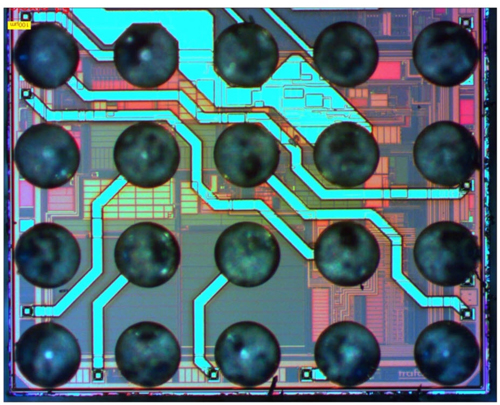
The application-specific microchip (ASIC), houses millions of circuits on an area of approximately 2.5 x 2.5 millimeters, where soldering points establish contact between the chip and the electronics of the pressure transmitter (Figure 7).
Conclusion
The best measuring results are obtained when the measuring cell and the microchip are precisely matched. For this reason, Trafag produces its own measuring cells and has developed its own ASIC. By developing these two key components under one roof, the pressure transmitter functions optimally, and quality and reliability can be guaranteed.
Do you have any questions about the design of the Trafag pressure transmitter?
We are happy to be of service to you. Please contact us.
Trafag's pressure transmitters
-
 NAI 8273Out of stock
 -
 FPI 8237Out of stock
 -
 NHT 8250Out of stock
 -
 FPT 8236Out of stock
 -
 NAE 8256Out of stock
 -
 CMP 8271Out of stock
 -
 EXNT 8292Out of stock
 -
 EXNAL 8858Out of stock
 -
 EXNA 8854Out of stock
 -
 EXNA 8852/8853Out of stock
 -
 ESH 8845Out of stock
 -
 EXNAL 8859Out of stock
 -
 NAL 8838Out of stock
 -
 ECR 8478Out of stock
 -
 ECTN 8477Out of stock
 -
 ECT 8473Out of stock
 -
 ECT 8472Out of stock
 -
 ECL 8439Out of stock
 -
 DPS 8381Out of stock
 -
 DPC 8380Out of stock
 -
 EPN-S 8320Out of stock
 -
 EPN/EPNCR 8298Out of stock
 -
 EPR 8293Out of stock
 -
 EPN 8288Out of stock
 -
 EPI 8287Out of stock
 -
 EPR 8283Out of stock
 -
 NPN 8264Out of stock
 -
 NAR 8258Out of stock
 -
 NAR 8258Out of stock
 -
 NSL 8257Out of stock