High-precision monitoring of the insulating gas density with reference gas comparison
The reference gas comparison principle was developed and patented by Trafag in the 1980s - and has become the leading industry standard for insulating gas density monitoring in high-voltage technology. If density monitoring must meet high requirements for reliability, accuracy, stability and durability, there is no way around is this fully temperature-compensated principle.
Gas density monitoring: temperature compensation is a must
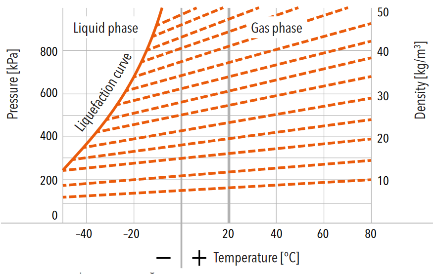
Density measurement in pressurized, gas-insulated chambers is all about physics, because pressure, density and temperature have a specific relationship. The relationship is defined by isochores (constant change of state) for each specific insulating gas. The insulating performance of a gas-insulated chamber is achieved by a defined density leading to a specific pressure at a given temperature. In a closed and gas-tight chamber, the total density always remains constant, but temperature variations lead to a variation of the system pressure.
Diagram: Lines exemplary representing constant SF6 gas density (isochores) - Changes in pressure and temperature with constant volume.
Vapor pressure curve: lines of equivalent gas density of SF6
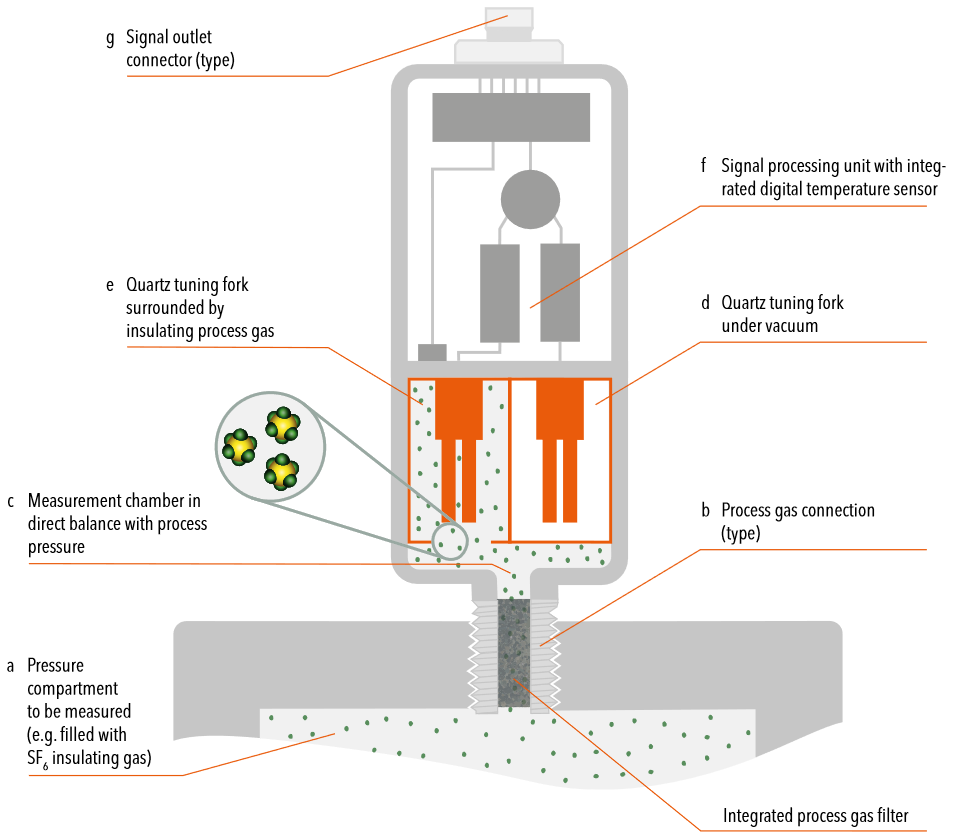
Schematic representation of the reference chamber principle: The reference chamber (f) is filled with the reference gas (c), which corresponds to the customer's specification, with a previously precisely defined gas quantity. In the reference chamber there is a bellows system (d, e), which is pressurized from below with the insulating gas (a) of the system to be monitored. Depending on the gas density or pressure, the bellows system moves and thereby triggers the customer-specifically set microswitches (h). The reference gas and the insulating gas to be monitored are thermally coupled by the bellows system and behave correspondingly identically. Such that the temperature has no influence on the monitoring. The measuring principle is fully temperature-compensated. It is therefore an absolute monitoring principle.
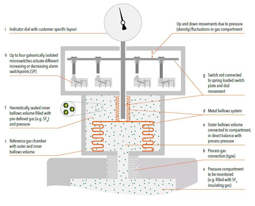
Absolute density monitoring allows full temperature compensation by reference system
A density monitor is usually mounted directly on the pressure chamber of the high-voltage system (a) via a configurable process connection (b). Trafag density monitors are based on a reference chamber (c) with an integrated metal bellows system (d), which is filled with the customer-specific insulating gas. The metal bellows system enables a direct temperature coupling of the pressure chamber gas and the insulating gas filling in the reference chamber. Changes in the ambient temperature affect the pressure (isochoric change of state) in the gas space to the same extent as the pressure in the reference chamber. Therefore, the influence of temperature on the insulating gas pressure is inherently compensated and a very precise insulating gas pressure @ 20°C (corresponds to density), at any ambient temperature, is shown on the display (i). No false alarm is triggered by temperature-related pressure changes. The reference chamber of the density monitor and the pressure chamber of the high-voltage system are both hermetically sealed systems. The ambient pressure (e.g. altitude or weather fluctuations) has no influence on the functional principle. It is therefore an absolute monitoring principle.
Bellows system actuates microswitches
The pressure, or more precisely the density, of the insulating gas compartment to be monitored is compared via the outer bellows volume (e) with the pre-defined density of the hermetically sealed inner bellows volume (f) of the reference chamber. If the density of the gas compartment changes, the bellows system actuates up to four independent microswitches (h) via a switching rod and a spring-loaded switching plate (g). Each microswitch can be calibrated at the factory for either rising or falling pressure, i.e. if the density falls below the pre-defined switching point settings, the microswitch contacts close or open stepwise. The switching point accuracy is tested at the factory at -25°C, +20°C and 50°C.
Supporting measures for demanding outdoor applications
If the insulating gas compartment pressure (a,e) drops due to leakage, the hermetically sealed inner bellows volume pressure (f) gains impact towards the dropping compartment pressure. Switch rod with switch plate (g) move down. If local environmental effects influence direct temperature coupling of the pressure chamber (a) and the reference gas system (c), e.g. in outdoor installations with strong solar radiation or rapidly changing or extreme weather conditions, specially designed thermal covers support the temperature balance between the pressure chamber and the reference gas system.
Practical example of the operation
The following example will be used to explain how the bellows system works. The customer-specific defined parameters in this example are:
- Filling pressure (density) of insulating gas compartment: 6.1 bar abs. @ 20°C, pure SF6
- SP1: 5.7 bar abs. @ 20°C, decreasing warning switchpoint for compartment re-filling
- SP2: 5.5 bar abs. @ 20°C, decreasing lock-out alarm switchpoint
- SP3: 5.5 bar abs. @ 20°C, redundant decreasing lock-out alarm switchpoint
- SP4: 6.4 bar abs. @ 20°C, increasing high-alarm switchpoint for compartment overpressure
- Factory pre-pressurised inner bellows volume of reference chamber: 5.7 bar abs. @ 20°C, SF6 hermetically sealed, according to SP1
First-alarm switchpoint
When the pressure drops below switchpoint 1 (SP1) at 5.7 bar abs. @ 20°C, the first microswitch switches and triggers the first-alarm. Usually, the first-alarm indicates that the pressure chamber needs to be refilled.
Emergency stop-alarm switchpoint
If the pressure drops further, in the example below 5.5 bar abs. @ 20°C, then two further, redundant microswitches (SP2 and SP3) usually switch. By default, these switchpoints are used as emergency stop; the operational and functional safety of the system is no longer guaranteed.
High-alarm switchpoint
A fourth microswitch (SP4) can be used, for example, to monitor unwanted overpressure conditions during pressure compartment re-fill routines. If the pressure rises above 6.4 bar abs. @ 20°C, the microswitch switches and triggers a high-alarm.