Venting pressure transmitters?
The reasons behind the process and the technical solutions on offer
When pressure transmitters measure relative pressure, the environmental or atmospheric pressure must be on the back of the measuring membrane. Because with conventional industrial pressure transmitters, this side is located within the housing, venting is required to equalize the pressure between the inside of the housing and the environment.
The simplest way to achieve the necessary pressure equalization mentioned at the beginning would be to have a hole in the housing. This would however allow the ingress of liquids and solid matter that have the potential to damage the transmitter from inside. Especially in harsh industrial environments, where construction machines are exposed to wind and weather for example, effective IP protection (Ingress Protection against gas and liquids) is crucial to ensuring that the pressure transmitter functions reliably.
Manufacturers of pressure transmitters have therefore developed a range of solutions that allow this pressure equalization to take place while still ensuring a high degree of IP protection. All of these solutions are always a compromise between effective venting and high IP protection on the one hand and low costs on the other. Without exception, they are worse than a hermetically sealed transmitter. This is why pressure transmitters are vented only when required by the operating conditions.
When is pressure equalization in the transmitter required?
Ideally, the pressure at the back of the membrane should be exactly the same as the ambient pressure. Only then can a precise relative pressure measurement be achieved. The pressure inside the transmitter is meant to adapt to the ambient pressure variations that can be caused by changes in the weather, diurnal variations or changes in the height above see level (in vehicles for example). If this does not happen, a measurement error occurs. Whether or not this measurement error can be tolerated depends on the measurement range: a change of 100mbar due to a change in the weather has a bigger impact when the measurement range spans just a few bar than it does at high pressures of several hundred bar. The required degree of accuracy also plays a role: the more accurate the measurement has to be, the less tolerable any deviation.
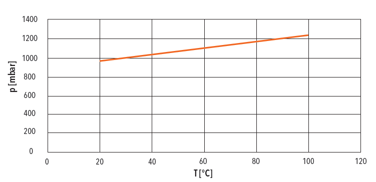
The heat-up of the pressure transmitter - and hence also the expansion of the air inside the transmitter - must also be taken into account. The air trapped inside the transmitter expands as the temperatures increase. If however the housing is hermetically sealed, the pressure inside increases and this causes it to push against the measuring membrane. The graph shows, based on the ideal gas equation, how the pressure inside the housing increases as soon as the trapped air warms up. To prevent this increase in pressure, the trapped air must either flow outwards or be able to expand freely in one direction.
Besides the question of whether a pressure equalization is necessary, the rate at which such equalization occurs is also important. This is because not all the solutions presented below offer the same rate of pressure equalization; some of them involve a slower rate due to the small flow cross-sections.
The time it takes for up to 90% of the pressure differential (a typical reference value) to equalize varies from just a few milliseconds to several minutes or even several hours in the case of extremely tight solutions. When is which time still acceptable? The answer to this question depends in turn on the application concerned: changes in the weather usually occur relatively slowly and even relatively tight transmitters are able to properly replicate such changes. The same goes for diurnal variations. Changes in the height above sea level, by contrast, can occur relatively quickly in certain situations, when rail vehicles cross mountain ranges for example. Extreme cases of such circumstances are aircraft and helicopters. In such applications, therefore, the absolute pressure is usually measured. The change in pressure brought about by a temperature change in the transmitter itself or in the environment is especially precarious and often underestimated: if an engine of a construction machine starts at a temperature around freezing, it will reach operating temperature within just a few minutes and heat up even those units that are not directly mounted to temperatures above 30°C. This is where efficient venting is essential to achieving correct measurement results.
What are the solutions?
Venting through the housing
Starting from the simple hole in the housing mentioned above, there are numerous ways of protecting this housing from environmental influences: the most common safeguards are mechanical covers or aeration diaphragms, gore membranes for example. These solutions offer the advantage of highly effective pressure equalization in general. To achieve this, however, the membranes need to be clean. But because pressure transmitters are often installed at exposed places, they are unprotected from oils, water and dust. During operation, these elements can develop into layers of dirt that plug the air duct leading inside the transmitter and hence stop the pressure from equalizing.
Another disadvantage is the relatively poor protection against aggressive cleaning agents or high-pressure cleaning methods. Gore membranes, therefore, should never come into contact with liquids as this will cause them to stop working. Solutions with mechanical protective caps are vulnerable to the ingress of water which can get inside the housing, in windy or rainy conditions or when slip streams are caused by rail vehicles, for example. Capillary effects through narrow gaps or a lower pressure inside the housing also allow liquids to penetrate the inside of the pressure transmitter. It is therefore necessary to ensure, even with good, tight designs, that the pressure transmitter remains relatively clean or is at least cleaned of dirt at regular intervals.
Venting through the cable
Another possibility for venting pressure transmitters concerns the electrical connection, i.e. venting through the plug or cable. Pressure transmitters with a connection cable attached directly can, in certain cases, be vented through the cable. The pressure is equalized through the small interspaces between the strands in the cable. The smaller these interspaces and the longer the cable, the less efficiently the pressure is equalized. Tests at Trafag have shown that with cables lengths of around two meters, it takes several minutes for any change in atmospheric pressure to be equalized inside the transmitter. Special cables with an integrated vent tube are used for long cables or whenever a change in pressure has to be equalized rapidly.
This plastic tube, which is located next to the strands inside the cable, ensures a reliable pressure equalization with the environment. Because the cable end is usually in a protected area, this solution is also suitable for transmitter installation locations that are prone to contamination. It is important to prevent the cable, and hence the plastic tube as well, being crushed or kinked over edges during assembly.
Venting through the plug
If venting is to take place through the plug, we should be aware that as well as being developed for pressure transmitters, plugs are also used as standard for numerous sensors and actuators. Venting, however, is relevant only to relative pressure transmitters. For other cases, a hermetically sealed plug is the ideal solution since this better protects the inside of the device.
In terms of pressure equalization, plugs can be divided into two groups. The first group comprises those plugs that fundamentally offer relatively low IP protection, e.g. plugs to EN 175301-803-A (DIN43650-A) or industrial standard (DIN 43650-C). Such plugs are not particularly tight against gases and almost always allow rapid pressure equalization. The second group comprises the somewhat tighter plugs, M12, Deutsch or MIL-C, for example. With these plugs, the venting process has to take a different form. Solutions with venting through the housing as mentioned above are employed, or venting occurs first through the inside of the plug and then through the cable. Venting via the cable provides the pressure transmitter with the best possible protection against contamination from outside. However, this solution requires a facility for venting at the cable end. The cables with molded plug or sheathing often used are not suitable in these cases. Cables with molded plug and sheathing are not entirely suitability, since the injected plastic penetrates the sheathing and hence allows minor pressure equalization.
Upon request, Trafag offers in collaboration with a cable manufacturer a version with molded M12 plug and integrated vent tube. Do you have applications that call for reliable venting? Are you unsure which pressure transmitter is the most suitable? Or are you already using pressure transmitters that deliver false measurements, which could be down to problems with the venting approach? Then reach out to us. Our experts will be happy to advise and liaise with you to find a solution that meets your pressure measurement requirements.
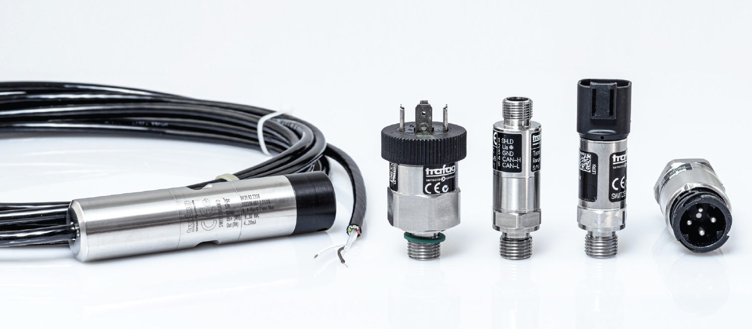
Comparison between various venting concepts for pressure transmitters. From left to right: vent tube in the cable (here with a level sensor); device plug to DIN 43650-A with low protection level; M12x1plug with hole in protected thread area (gore membrane not visible); Deutsch plug with vent hole in the housing (gore membrane not visible); MIL-C plug with hole and gore membrane for venting through the cable.
Do you have questions about our pressure transmitters and their venting?
We'd be glad to help. Please get in touch with us.
Ideal gas equation
The theory of ideal gases describes the behavior of a gas using a simple formula.
pV=nRT
p=absolute pressure
V=volume
n=number of gas molecules (in moles)
T=temperature (in K)
R=ideal gas constant
For a constant volume of gas, the equation is transformed in order to set various states in relation to one another.
p1V1 / T1 = p2V2 / T2
For the deliberations of a pressure change in pressure transmitters, the trapped air can be considered the ideal gas in simple terms. Also in simple terms for the small temperature changes, the volume can be considered constant. Hence, the ratio of pressure to temperature must remain the same at all times. In other words, the pressure rises proportionate to the increase in temperature.
p1V1 = p2V2
Products
-
 NAI 8273Out of stock
 -
 FPI 8237Out of stock
 -
 NHT 8250Out of stock
 -
 FPT 8236Out of stock
 -
 NAE 8256Out of stock
 -
 CMP 8271Out of stock
 -
 EXNT 8292Out of stock
 -
 EXNAL 8858Out of stock
 -
 EXNA 8854Out of stock
 -
 EXNA 8852/8853Out of stock
 -
 ESH 8845Out of stock
 -
 EXNAL 8859Out of stock
 -
 NAL 8838Out of stock
 -
 ECR 8478Out of stock
 -
 ECTN 8477Out of stock
 -
 ECT 8473Out of stock
 -
 ECT 8472Out of stock
 -
 ECL 8439Out of stock
 -
 DPS 8381Out of stock
 -
 DPC 8380Out of stock