FAQ: Insulating gas density monitors and sensors
Do you have any questions on gas density monitors or sensors? First answers can be found here in our FAQ.
Countermeasures against aggressive SF6 by-products
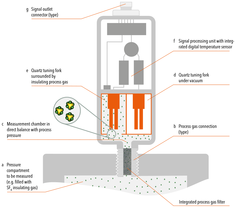
SF6 is inert during normal use. When electrical discharges occur within SF6 filled gas compartments, mechanical abrasion, toxic and material-aggressive by-products can emerge. The two main by-products that may occur are hydrofluoric acid and thionyl fluoride. Both can cause long-term damage to improper material selection. Abrasion particles can cause sensing element degradation. Trafag deals with it by using suitable materials and additional integrated process gas filters.
Materials for process gas connection, reference gas chamber and bellows system are specifically selected to withstand hydrofluoric acid and thionyl fluoride. High-alloyed stainless steels 1.4404, 1.4435, 1.4571 (AISI316L, AISI316Ti) are used.
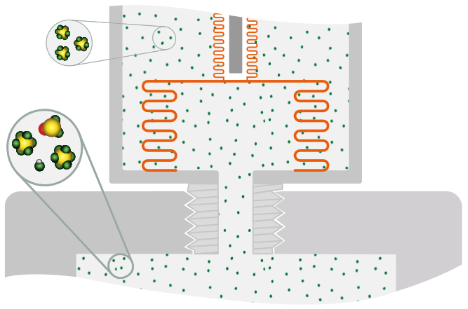
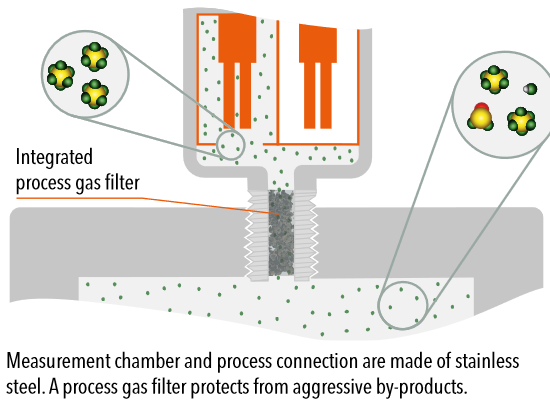
The quartz tuning fork requires advanced countermeasures to repel ingress of aggressive by-products that may occur in insulating gases. Materials for the process gas connection and measurement chamber are specifically selected. High-alloyed stainless steels 1.4404 and 1.4435 (AISI316L) are used. An additional integrated process gas filter protects from fine abrasion particles and absorbs corrosive gases.
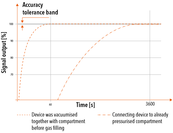
During normal operation, insulating gas density changes are detected in less than 10 ms. The integrated filter element induces a transient response time after installation and initial insulating gas filling. Therefore, a minimised time period for gas equalization between process compartment and the sensor's measurement chamber occurs.
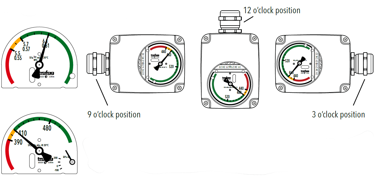
Trafag provides maximum flexibility in customization for the indicator dial with a full variety of colour codings and pressure units including dual range indication. This also includes rotated dial orientation by 90°/180°/270° to provide best readability for restricted installations.
An optional low-pressure indicator monitors conditions aside normal operation e.g. while compartment is filled with transport pressure or being vacuumed.
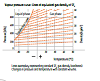
Arctic climate presents the highest requirements to gas compartment and density monitoring. The main safety aspect is the alarm when the insulating gas may liquefy.
Low temperatures can lead to liquefaction of process gas. Liquefaction causes a rapid pressure-drop that can temporarily trigger an alarm switchpoint. Gas density monitor 87x8 keeps the alarm status until the alarm trigger level is exceeded again while returning to normal condition.
![Diagram: Pressure [kPa] / Temperature [°C] of Liquefaction curve](https://www.trafag.com/media/Knowhow/faq-gas-density/liquid-phase.png)
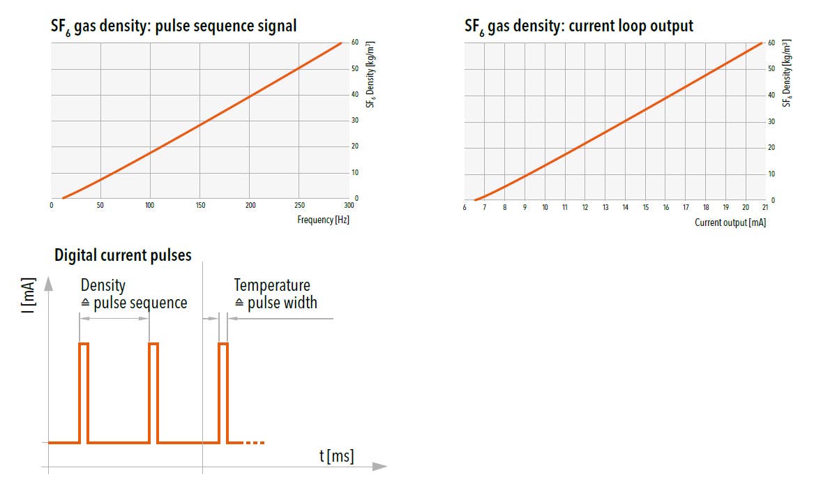
The digital pulse-width modulation features density and temperature data. Trafag provides conversion formulas for gas density, standardised gas pressure @ 20°C for SF6 or alternative insulating gases and for the conversion of pulse-width to temperature.
The current loop output has a resolution of 6.5 … 20mA. Trafag provides conversion formulas for gas density and standardised gas pressure @ 20°C for SF6 and alternative insulating gases.
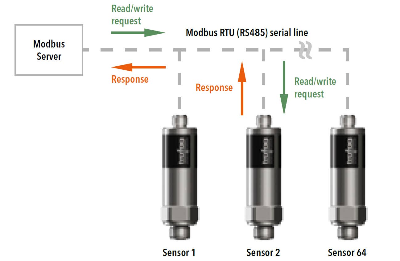
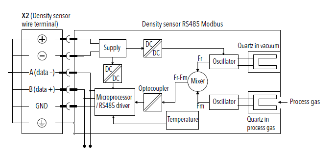
The open available Modbus protocol is the ideal communication layer for transmitting data between electronic devices over serial RS485 lines. It is a client/ server protocol. One client controls the data transactions with multiple servers (sensors) that respond to the client's requests (read or write data). In a standard Modbus serial network, there is one client and up to 64 servers (sensors), each with a unique server address.
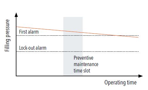
Density measurement is provided via 2-wire current loop output. It provides essential trend information of potential gas losses or gear status and therefore allows to determine preventive maintenance measures.
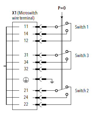
Density monitoring is based on up to three galvanically isolated microswitches that actuate different alarm signals.
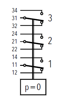
Density monitoring microswitches and sensor data signal are separated by independent wire terminals.
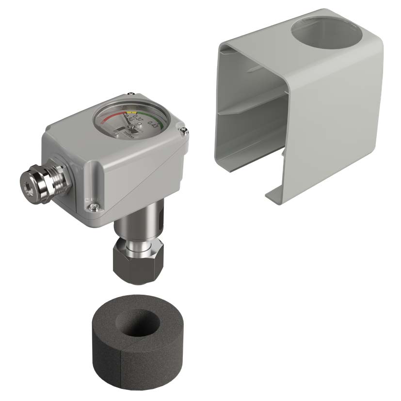
Weather protection cover with separate thermal insulation ring
The weather protection cover is aimed for long-term element protection of the density monitor. The insulation ring for the probe housing increases thermal inertia in moderately changing climates. The probe housing is the lower part of the monitor where the reference gas chamber and the oscillating quartz sensor are located.
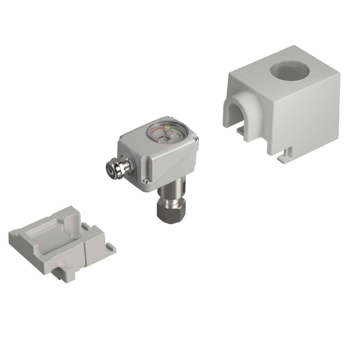
Thermal foam cover
The thermal foam cover is aimed for long-term element protection and dedicated thermal inertia of the density monitor. It is recommended for outdoor installations with high solar radiation or extreme diurnal temperature fluctuations (e.g. high altitude, arctic, desert).
Compartment immersion process connection
The compartment immersion is an intank pressure connection installation that is aimed to match continuously process gas and monitor probe temperature. This allows to further minimize a temperature disbalance between reference chamber and gas tank. A bayonet fitting with integrated stop valve allows installation while process compartment is pressurised.
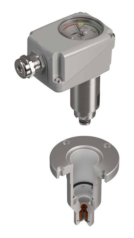
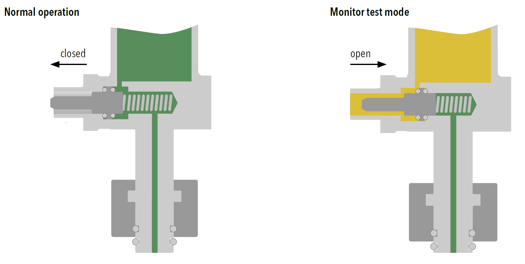
Integrated density monitor test valve
Greenhouse regulations require regular verifications of the used equipment. The test valve allows in-situ microswitch point or sensor checkings without dismounting the monitor from the pressure compartment. Test equipment is connected via a standardised DN8 port during normal operation under nominal system pressure.
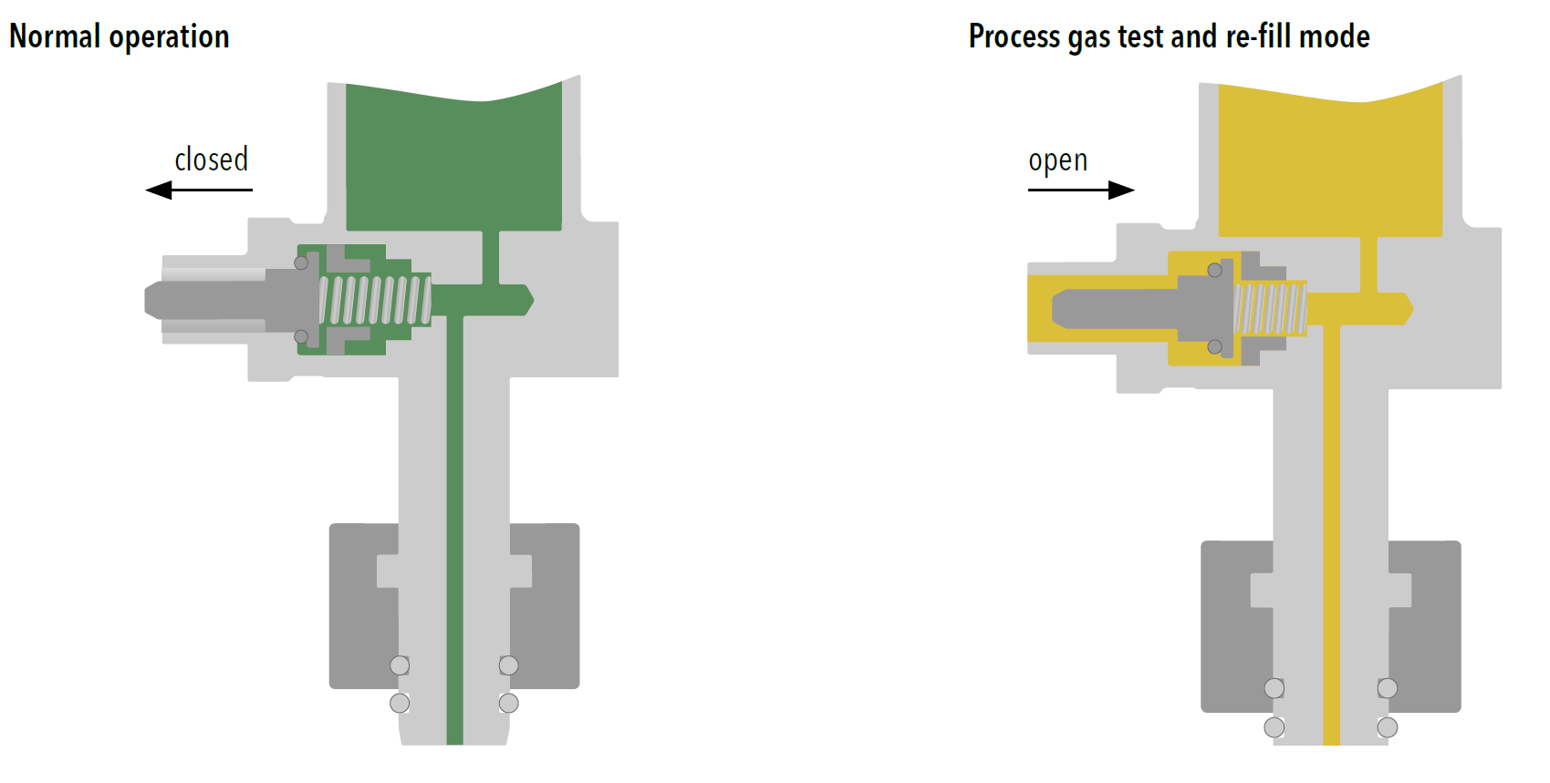
The test and re-fill valve offers two essential functionalities. Firstly, it provides the capability to analyze in-situ the gas quality of the pressure compartment. On the other hand, it is a re-filling valve that allows direct insulating gas replenishment of the pressure compartment. Test or re-fill equipment is connected via a standardised DN8 port during normal operation under nominal system pressure.
If you have further questions, do not hesitate to contact us.