Advantages of smart parameterisation using an app
Electronic pressure transmitter and switch with display
Pressure sensors with display – also often called display pressure switches – are very widespread today: On the one hand, they permit electronic pressure measurement with a continuous, analogue output signal. On the other hand, they have one to two freely configurable switch outputs, which can be configured directly on site through a display. This advantage is significant when the controller, with all system parameters displayed, is far removed from the measurement point, but the machine or system operator needs the information about the measurement value to manually intervene in the operation, for example. This is frequently the case with water treatment plantsor for fill-level monitoring of tanks in processing systems: Here, the pressure is directly measured at different places in the system, such as tanks, pumps, valves, filters, etc. But the system controller itself is located in another part of the building. If the valves need to be opened or closed due to an operating malfunction or servicing - for example, to identify a cause of the malfunction - the system operator can check the effects of his or her interventions directly on the measurement point through the pressure sensor display.
With Trafag’s pressure sensors: meaningful values where needed
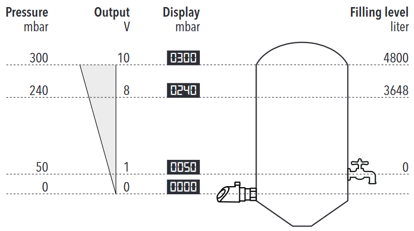
Normally, the pressure sensor display only shows the pressure that it measures at the location. This value is compared to a setpoint in the system controller or - in the case of fill-level monitoring - converted to the level through the density of the liquid. This is not automatically possible on the display. For cost reasons, standardised interfaces are almost always used, which in the case of sensors only have an output signal. This makes genuine two-way communication with the system controller impossible. For this reason, the pressure value from the controller cannot be transmitted to the local pressure sensor, or the value cannot be shown on the display. Trafag’s pressure transmitters and switches with display now offer the ability to configure the display through the Android app so that meaningful values, not just pressure, are displayed to the operator. The functions the Trafag devices offer will be shown using some practical examples.
Display value in percent
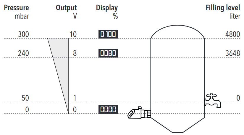
If a different nominal pressure exists at different locations in the system – e.g. with multi-stage pumps or tanks with different contents – the operator must know which value is really required for each measurement location. This is often impractical and subject to error, especially in case of malfunction, when the displayed value has to be classified under time pressure. It is better if the measurement value is simply displayed as a percentage at each measurement location. Together with the possibility to scale the measurement range in the device by up to 50%, the 100% value can be adapted precisely to the target value.
User-defined display value
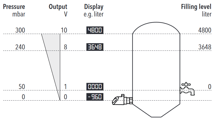
In some cases, we want to know more than the percentage of the measurement range, such as the tank content still present in litres. The display value can be parameterised with the Trafag pressure transmitter and switch: Both the lower and the upper limit value can be entered with any value desired.
For design reasons, the pressure sensor can be attached below the minimum level, such as below the regular drain. But there is still pressure, due to the remaining tank contents, which are no longer available for the process. The value at zero pressure can be parameterised with a negative number, so the display effectively shows zero when the minimum level is reached. But this setting only influences the display value, not the analogue output signal. A formula must be stored in the controller to make such a correction.
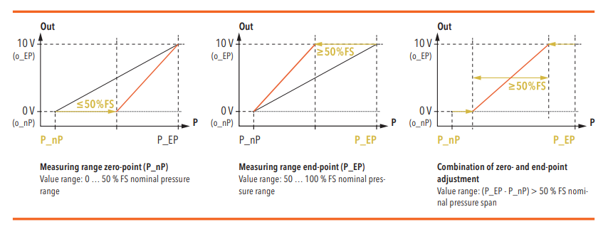
Scalable and movable measurement range
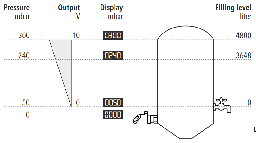
If the output signal should show the lower limit value at a higher pressure within the measurement range than zero pressure, this must be carried out by parameterisation of the measurement range. To do this, the lower limit point of the measurement range can be increased by up to 50% of the measurement range by means of an additional function. The limit point can be shifted downward by up to 50% of the measurement range even in the standard version. Through the combination of these two functions - that is, through adjustment of the zero point and limit value of the measurement range - the output signal can be parameterised to any range desired within the original measurement range. But the remaining measurement range must be at least 50% of the original range (see graphic).
Adjustment of the output signal
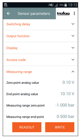
Some of the common standard output signals have 0 V as the lower limit value. But this makes detection of a cable break impossible. For that reason, the output signals can be adjusted independently of the set measurement range: For example, a 0…10 VDC output signal can be parameterised to 0.1…10.1 VDC. With the same range of 10 V, this forces a minimum signal level of 0.1 VDC and so makes loose connections or cable breaks easy to detect.
Many options – easy parameterisation using the Android app
These numerous setting options can be made with both the keys on the display and with the Android app through the NFC interface. Parameterisation can be easily performed and checked in the app’s clear menu. Moreover, stored parameter sets can be loaded directly from the smartphone app to the sensor. This simplifies parameterisation considerably (for example, with replacement parts) and makes replacement more secure.
These numerous possibilities for parameterisation of display, measurement range and output signal can also be combined. But they can also influence each other so that undesired effects occur. If this should happen, the Factory Reset can be used to reset all values to the original condition and start the process over again.
Features
- Parameterization also via NFC-smartphone app (Android)
- Display and electrical connection are independently rotatable 335°/343°
- Analogue output switchable mA or V
- Integrated datalogger
- Measuring range adjustable
Would you like to read the whitepaper later?
Do you have any questions about our Pressure sensors with display?
We'd be glad to help. Please get in touch with us.


