Trafag revolutionises the measuring of highly dynamic pressure curves
Trafag has succeeded in unifying the highly dynamic response behavior of a test bench sensor and the extreme robustness of a mobile hydraulic pressure transmitter by combining thin-film-on-steel measuring cells and an ASIC developed in-house. The Trafag ASIC TX with an innovative parallel mixed-signal structure is the key to a response behaviour at nearly unlimited speed.
In many applications, above all in the testing field, the aim is to record highly dynamic pressure curves, e.g in order to analyse the opening and closing performance of valves, track pressure curves of explosions and explosive pressure expansions or to examine brief pressure peaks in hydraulic systems. Transmitters for industrial applications on the market are generally not capable of adequately capturing such high-frequency signals, be it because the internal electronics are not efficient enough or because the signal is deliberately dampened so that the control system is not overloaded with unnecessary information. That is why special pressure transmitters are offered on the market specially developed for high speed applications. These transmitters are designed with cut-off frequencies (see box) of 5 to 50 kHz and have certain advantages and disadvantages often originated in the sensor technology which is used.
The piezoelectric sensor technology has always been most common for measuring highly dynamic pressure curves. In purely theoretical terms, this physical measuring principle is the most appropriate one because it only provides a signal during dynamic pressure curves, but with a very good signal-to-noise interval and for high frequencies. Another advantage is the principally high rigidity of the construction that allows very high natural frequencies. On the other hand, disadvantages of this technology are the high costs due to the very sensitive and sophisticated production and the complex signal evaluation (charge amplifier) as well as the drifting vulnerability of the zero point, which is often accepted by many users because of a lack of suitable alternatives.
A significantly less expensive alternative is the piezoresistive measuring principle, which allows for relatively simple amplifier electronics thanks to a very good signal-noise ratio, which is however inferior to the piezoelectric principle with respect to dynamic and above all rigidity as a result of the sensor construction which is filled with oil. Yet the main disadvantage of the piezoresistive technology is the drifting vulnerability which is particularly apparent at high temperatures.
Alternative: thin-film-on-steel technology combined with ASIC
With respect to drifting, thin-film-on-steel technology is without a doubt the best, allowing high frequencies but having a very small signal-to-noise ratio in comparison to the other two. Particularly when it comes to the evaluation of highly dynamic signals, this places such high demands on the evaluation electronics in the transmitter that most manufacturers of high-speed pressure transmitters fall back to one of the other sensor technologies. Trafag, one of the pioneers, with nearly 35 years of experience, has a different approach: by using the self-developed ASIC (application-specific integrated circuit), tailored precisely to the requirements of the Trafag sensor technology with specific amplifier and filter functions, the disadvantages of the low signal-to-noise ratio could be eliminated and the sensor technology, superior with respect to robustness and long-term stability, can be used even in situations where other manufacturers reach their limits. Because of the coordinated development of the two core technologies - the thin-film-to-steel sensor element and the ASIC- Trafag can combine the responsiveness of a high-speed pressure transmitter with the robustness of a pressure transmitter built for the harshest environments.
During production each pressure transmitter is individually adjusted by calibrating against high-precision pressure standards. During this process, correction parameters for the linearization, zero point and span correction are saved on a chip in the transmitter, in this case directly in the Trafag ASIC. The sensor element consists of sputtered thin-film resistors in a Wheatstone bridge arrangement which are compressed or expanded depending on the pressure induced membrane deformation. Every input signal of the sensor element resulting from the deformation induced change of resistance, is corrected accordingly to the parameter saved in the ASIC, particularly with regard to linearity, zero point and span as well as temperature compensation above or below 25°C.
Unlimitedly fast pressure transmitter
The Trafag ASIC TX, that joins more than 100,000 transistors on an area of just 2x2 mm, consists of two central elements: an extremely high-performance analogue amplifier part and an ideally matched digital part. The input signal of the sensor element is corrected by the analogue amplifier up to 98–99 % and then transmitted to the signal electronics in real time. The digital part is only necessary for the remaining 1–2 % of the correction value which then mixes with the analogue amplifier signal. The strength of this concept is the very high signal processing speed (except for the digital part correction), that is completely independent from the sampling rates of Analogue-Digital (A/D) and Digital-Analogue (D/A) converters; only slightly limited by the analogue part of the electronics. This makes a Trafag pressure transmitter generically extremely fast, and it is normally electronically dampened in order to be suitable for the corresponding applications and resistant to interferences (e.g. EMC).
In normal industrial applications without special requirements for signal speed, engineers aim for an optimal compromise between robustness and sufficiently fast responsiveness to get the desired measuring results. Regardless of the chosen sensor principle, high signal speeds generally require an extensive wiring effort as specially shielded cables must be used. Generally, the shielding must be done very carefully in order to avoid for example feedback, which due to supply voltage ripple appears on both the transmitter and the evaluation unit.
On the other hand, there are also applications where high signal dampening is desired, usually in normal industrial pressure transmitters: for example in order to smooth out high frequency signal ripples from mechanical liquid pumps already at the transmitter instead of in the control.
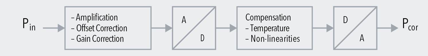
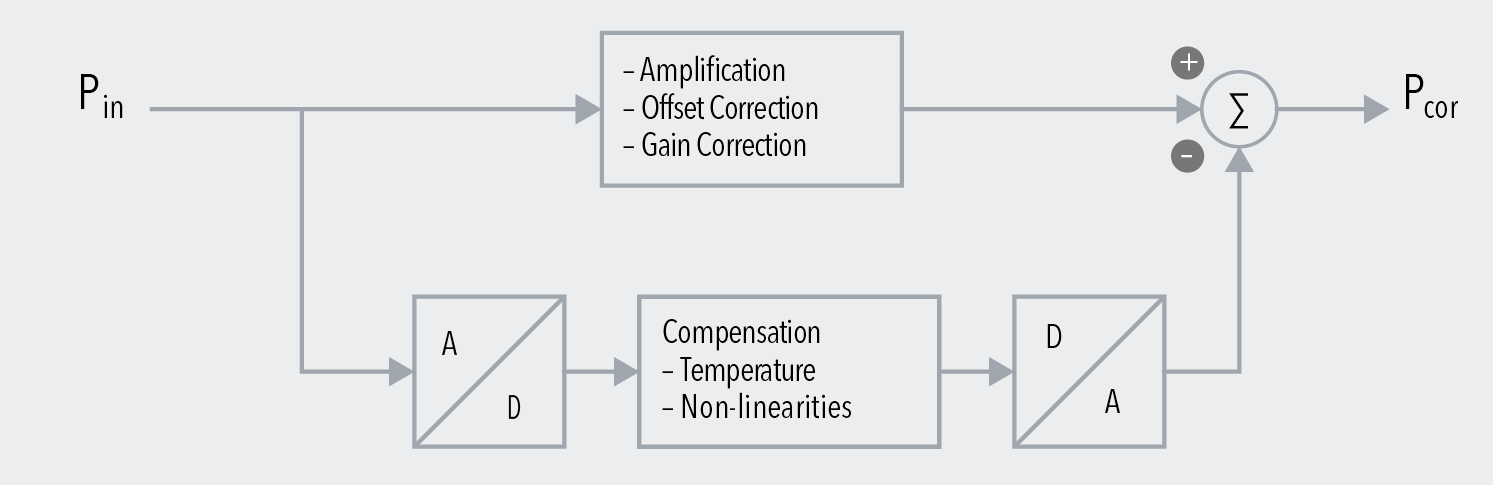
Schematic design of the ASIC TX
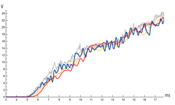
The conventional design (diagram above) with fully digital signal processing is limited by the speed of the A/D or D/A converter. The Trafag design (diagram below) consists of two signal components, provided that the main path (about 98 % of the signal) is purely analogue in amplification and zero point and span correction and therefore very fast. Only the correction signal (temperature and non-linearities) is comparatively slow. This part is not time-sensitive since temperature changes also exhibit response times in the minute range. Only the non-linearities correction is relevant in this part, which in the case of Trafag sensors makes up only about 1 % of the signal. Therefore only about 1 % of the signal depends on the speed of the converter.
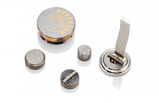
Pressure transmitters NAH 8254: For rough applications
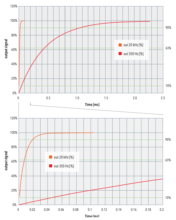
Based on the proven industrial transmitter NAH 8254 in the miniature size of 19mm width across flats, Trafag offers special versions for which the desired cut-off frequency can be selected from various levels of over 20kHz (this corresponds to 18µs rise time, 10…90% nominal pressure) for highly dynamic pressure measurements down to 11Hz for a maximum signal smoothing. Both, the thin-film-on-steel sensor element and the basic design of the transmitter have been proven under extreme conditions (vibration, shock, temperature change, high pressure peaks, etc) in the harsh environment of construction and forestry machinery and guarantee a robustness and reliability that is unsurpassed in the measuring and testing field.
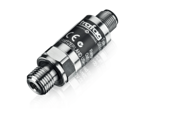
Pressure transmitter NAH 8254 with cut-off frequency 20 kHz for measuring highly dynamic pressure gradients: It combines the robust design of a mobile hydraulic transmitter with refined, extraordinarily fast electronics.
Data sheet: www.trafag.com/H72304
Cut-off frequency
For amplifiers, the cut-off frequency is the frequency at which the original signal amplification becomes 3 dB smaller than the maximum amplification. A signal with a higher frequency than the cut-off frequency is still rendered but is significantly less dynamic and accurate.
Sampling rate
The frequency with which a digital signal processing unit samples and processes a continuous, analogue signal. If the sampling rate is not twice as fast as the highest frequency occurring in the original signal anymore, aliasing effects can occur which can lead to signal distortion (Nyquist-Shannon sampling theorem).
Rise time
The time that elapses until an output signal level reaches a predefined value after an ideal, rectangular input signal pulse, e.g. 90% of the actual value. Rise time conversion (tr = rise time) in the cut-off frequency (fg): fg = 1 / (2π∙tr/2.2)
Bandwidth
The frequency spectrum between the lower and upper cut-off frequency, for pressure transmitters generally between 0 Hz and the maximum cut-off frequency.
Would you like to read the whitepaper later?
Do you have any questions about the measuring of highly dynamic pressure curves? We'd be glad to help. Please get in touch with us.
Recommended products
-
 NAH 8254 20 kHzOut of stock